SurfaceTreat
PLASMA – green technology of surface treatment
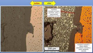
Cast iron with spheroidal graphite after galvanic treatment ZnNi and powder coating – microsection of the defect
Sample encapsulated in thermo set resin DuroFast180°/325 bar/5 min., glazed using colloid silica, photo Leica DM 2500 (left side figure), deposited by FeO – 3 min. / 3 mA (right side figure). Benefit of application after sputtering visual in the area marked with arrows (click for zoom).
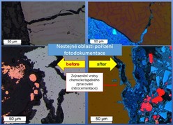
Fe3Al (experimental material developed and tested by Technical University in Liberec, (Mechanical Engineering faculty, Department of materials) – visualization of surface layer after nitrocarburising.
Sample encapsulated in thermo set resin with Cu filler, glazed using colloid silica, photo Leica DM 2500 (left side figure), deposited by FeO – 4 min./2,7 mA (right side figure). Benefit of application after sputtering visual in the area marked with arrows (click for zoom).

AlSi cast after anodizing and coating – visualization of metallic filler coloration in paint
Sample encapsulated in thermo set resin EpoFix, glazed using colloid silica, photo Leica DM 2500 (left side figure), deposited by FeO – 5 min./1,7 mA (right side figure). Benefit of application after sputtering visual in the area marked with arrows (click for zoom).
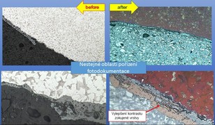
Flaked layer on the stell surface
Sample encapsulated in thermo set resin DuroFast, glazed using colloid silica, photo Leica DM 2500 (left side figure), deposited by FeO – 3 min./3 mA (right side figure). Benefit of application after sputtering visual in the area of the basic material (steel) mainly in different coloration of ferrite and pearlite (click for zoom).
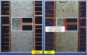
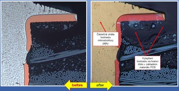
PCB after soldering using Sn solder – visualisation of so called barrel crack
Sample encapsulated in thermo set resin EpoFix, glazed using colloid silica, photo Leica DM 2500 (left side figure), deposited by FeO – 4-5 min./2 mA (right side figure). Benefit of application after sputtering visual in the area marked with arrows (click for zoom).
PCB after soldering using Sn solder – interference contrast of the basic material PCB and Cu layer
Sample encapsulated in thermo set resin Technovit 4001, glazed using colloid silica, photo Leica DM 2500 (left side figure), deposited by FeO – 3 min./3 mA (right side figure). Benefit of application after sputtering visual in the area marked with arrows (click for zoom).
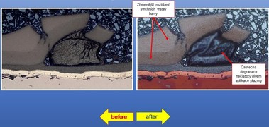
Steel forged piece after surface galvanization using ZnNi and multilayer lacquering – microsection in the impurity between the lacquer layers
Sample encapsulated in thermo set resin DuroFast 180° / 325 bar / 5 min, glazed using colloid silica, photo Leica DM 2500 (left side figure), deposited by FeO – 3 min./3 mA 2x (right side figure). Benefit of application after sputtering visual in the area marked with arrows (click for zoom).
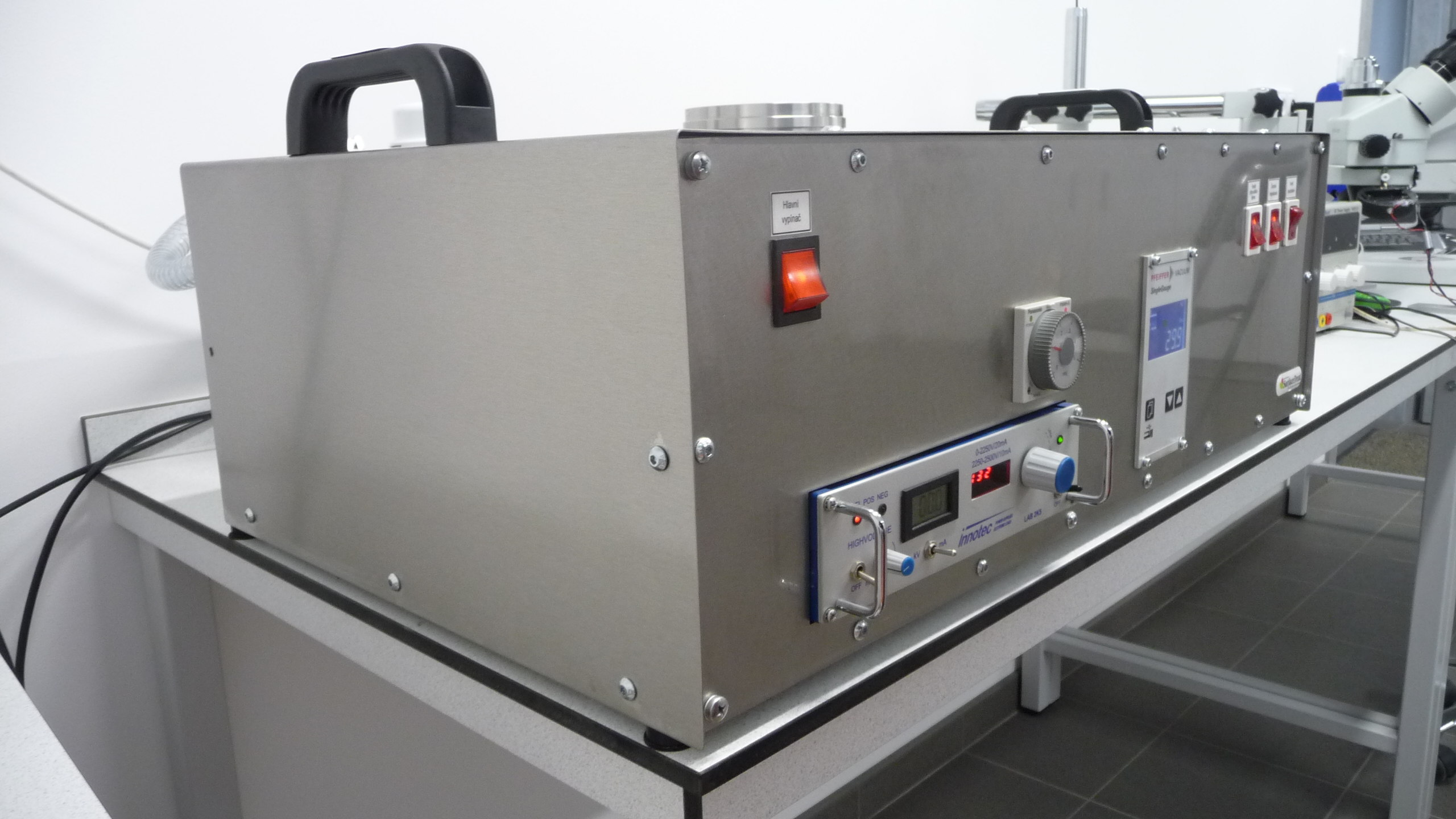
Description of the equipment for contrast enhancement on interface of materials in optical microscopy – Contrast enhancement chamber
- Main switch
- Vacuum chamber
- Venting valve
- Angle valve (Avoid damage of the plastic knob. Handle with care!)
- Dosing valve
- Vacuum gauge – in front, sensor on the back side
- Rotary pump with oil filter in the gas outlet
- High voltage supply
- Timer
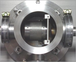
Detail of the vacuum chamber
a) Detailed view of the vacuum chamber with sample holder in place
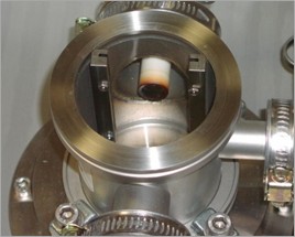
Detail of the vacuum chamber
b) Detailed view of the vacuum chamber; the sample holder is removed and the iron target can be seen